A dip meter is used for adjustment of radio equipment and antennas. The DM-81 is a self-excited oscillator designed for external coupling to the equipment being tested. It features both inductive and capacitive coupling for measuring enclosed coils and toroidal coils (patent pending). This is not possible with conventional testing instruments.
The DM-81 has the following two functions:
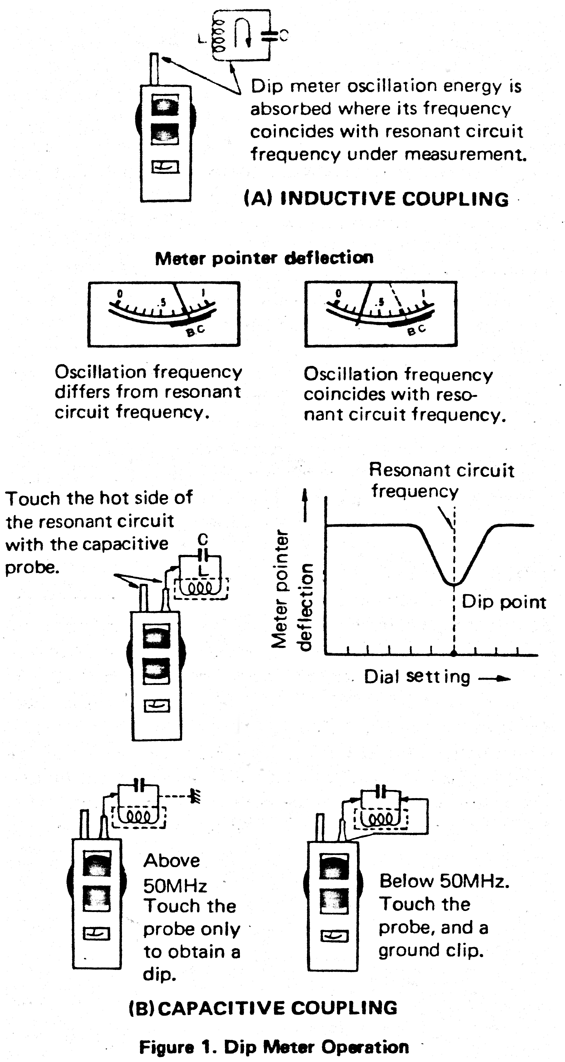
As shown (Figure 1A), place the coil unit of the dip meter in close proximity to the circuit being measured.
Adjust the dial. When the dip meter oscillation frequency coincides with the resonant frequency (tuned circuit), oscillating energy is absorbed by the circuit, thus decreasing the oscillation strength.
This strength is indicated on the meter. The pointer swings back momentarily at the resonant point. Since the meter pointer dips at a tuned point, this instrument is called a dip meter.
This is a special feature of the DM-81 which is not found in any other dip meter. The resonant frequency can be checked simply by touching the capacitance probe to the hot side of the resonant circuit under test, instead of coupling the DM-81's coil and measuring inductively. The frequency is read directly on the dial. See Figure 1B.
Radio equipment is miniaturized and most coils are enclosed in metal shields. Also, toroidal coils are used in many types of radio equipment, and these coils do not couple to conventional dip meters. The DM-81 has solved this problem.
| Frequency range: | 700 kHz - 250 MHz (± 3%)
A band 0.7 - 1.6 MHz (± 3%) B band 1.5 - 3.6 MHz (± 3%) C band 3.0 - 7.4 MHz (± 3%) D band 6.9 - 17.5 MHz (± 3%) E band 17 - 42 MHz (± 3%) F band 41 - 110 MHz (± 3%) G band 83 - 250 MHz (± 3%) |
| Modulation: | 1 kHz (sine wave) |
| Power requirements: | Battery, 9V(006P) |
| Power consumption: | 9 mA |
| Semi-conductors: | 1 FET, 3 transistors, 3 diodes |
| Crystal oscillator element to be used: | HC-25U and FT-243 |
| RF search terminal: | For measuring resonant frequency (capacitive coupling) and checking RF voltage using the supplied probe. |
| Earphone terminal: | Accepts crystal earphone with 3.5ø plug for monitoring modulated tone. |
| Dimensions: | 70W x 180H x 45D (mm) |
| Weight: | Approx. 690g (with accessories) |
| Accessories: | (1) Coils, A-G bands — 7 pieces
(2) Probe — 1 piece (3) Ground clip — 1 piece (4) Crystal earphone — 1 piece (5) Battery, 006P — 1 piece |
CAUTION: Do not apply a voltage exceeding 500V (DC + AC peak) to the probe.
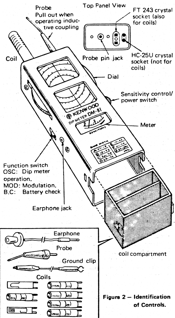
Taking the coil compartment out, you will find a battery snap connector inside the unit. Fit the snap to the battery. First lay the battery take-out ribbon into the battery holder, then install the battery in place. Place the supplied oscillation coils into the coil compartment and reinstall into the dip meter main body.
Verify that the battery is serviceable before operating your DM-81. First, turn the POWER switch on. Set the FUNCTION switch to "BATT CHECK". The battery is usable as long as the meter pointer is within the "B.C" zone. A low battery results in weak or unstable oscillation, no oscillation, or frequency error. Replace the battery when weak.
After use, be sure to turn the POWER switch off. If your DM-81 will not be used for a long period of time, remove the battery. You can easily remove it by pulling the take-out ribbon toward you. Never remove the case screws.
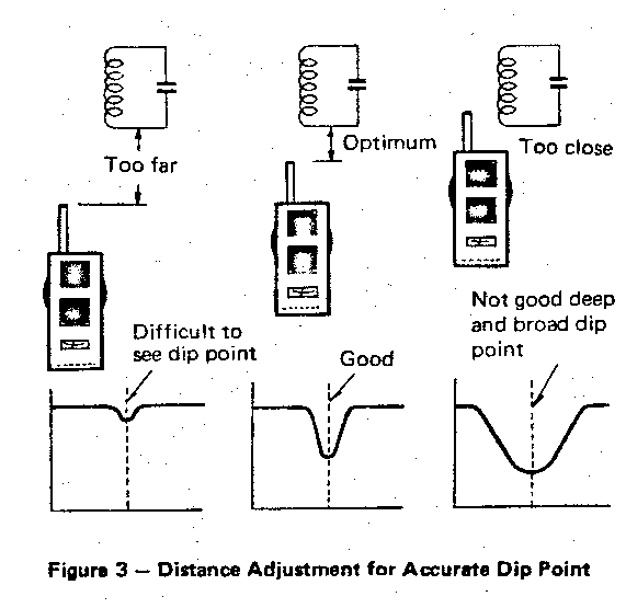
The closer the dip meter is brought to the resonant circuit being checked, the tighter the two are coupled and the deeper the dip point. However, the tuning point becomes so broad that you cannot find the correct resonant frequency. Therefore, it is advisable to move the dip meter a little away from the circuit.
Note that the A band has a large pull-in effect and therefore the dip point is broad.
There is no load problem in measuring vacuum tube resonant circuits. In measuring some resonant (tuning) circuits in transistorized transmitters and receivers, the resonant point cannot always be found by the dipping load. In this event, temporarily disconnect the transistor or operate the given resonant circuit with power on and measure by absorption.
Your DM-81 is usable as an absorption frequency meter in measuring transmitter power amplifier tank circuits and similar stages producing high RF energy. In measurement, do not abruptly bring the dip meter close to the circuit as the transistors and other parts in the dip meter could be destroyed by excess RF energy. Bring it near the circuit slowly while observing the meter pointer.
The meter pointer may swing slightly as if indicating a dip. This results from a variation in oscillation signal strength while tuning the oscillator variable capacitor. Move the dip meter coil away from the circuit under measurement. The meter pointer will return to full scale for a real dip.
Note: At first, couple the dip meter coil tightly to the given tuned circuit so that you can easily find the dip point. Then, bring the oscillation coil away until the dip is as narrow as possible, and readjust the dial precisely for an accurate dip point. Now read the correct frequency on the dial.
A basic measurement with your DM-81 is a frequency check of resonant (tuned) circuits comprised of coils and capacitors. In practice, the dip meter is brought near the coil to be measured as shown in Figure 1A. This illustrates a standard method of resonant frequency measurement.
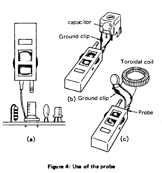
If a coil to be measured is located in a narrow place and cannot be coupled to the dip meter coil, or if a coil is enclosed in a shield, the probe can be used for accurate measurement. See Figure 4.
The dip point can be obtained by using the ground clip and probe for frequencies of about 50MHz or lower, and the probe only for about 50MHz and higher. Toroidal coils can be measured in the same manner. Note that the probe should be connected to the hot side (not the ground side) of the circuit. See connections (a) through (e) in the illustration. The dip point is sometimes critical depending on the circuit or frequency to be measured. An accurate dip point can be obtained by turning the dial slowly.
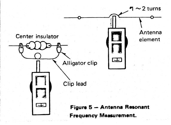
Any antenna can be regarded as a kind of resonant circuit. Its resonant frequency, therefore, can be measured as illustrated in Figure 5. For measurement, connect a one-turn coil to the feed point at the center of the antenna.
Couple it with the dip meter coil. Now, you can obtain the antenna resonant frequency in a similar manner to APPLICATIONS Section A. For a vertical antenna or similar antennas for which the other feeder lead is grounded, place the one-turn coil between the antenna and ground.
Couple the one-turn coil to the dip meter until a dip point is obtained. Then, slowly separate the coil to measure the resonant frequency accurately.
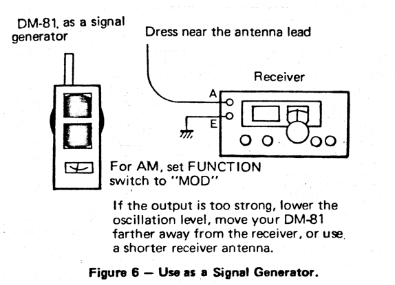
Your DM-81 can be used as a signal generator for aligning receivers and similar equipment. Couple the dip meter to the antenna circuit of the receiver as illustrated in Figure 6. The dip meter output carrier will enter the receiver. For aligning an AM receiver, set the FUNCTION switch to "MOD". The receiver will sound a 1kHz tone. Aligning SSB and CW receivers can be achieved by leaving the switch at "OSC" for no modulation. Adjust the capacitor trimmers and inductor cores for maximum receiver "S" meter reading or maximum speaker output.
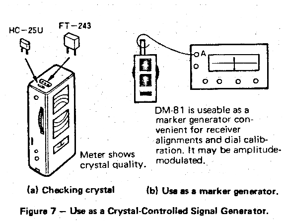
Your DM-81 car, be modified as a crystal checker by installing a crystal in Place of the oscillation coil (see Figure 7).
You may use either HC-25U or FT-243 crystals. Also, an HC-6U crystal can be checked if plugged into the FT-243 socket. The oscillation signal strength may vary depending on the type and frequency of the crystal used. Adjust the dial for most stable oscillation.
In addition, your DM-81 is applicable as a marker generator by installing a marker crystal of 1MHz, 3.5MHz, or the like. The marker generator is useful for calibrating a receiver dial.
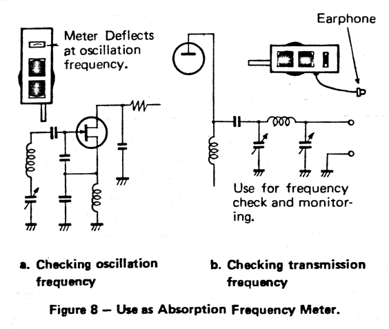
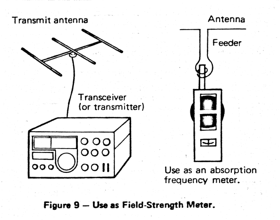
Install an oscillation coil covering the desired frequency range into the socket. Turn the SENSITIVITY control ON and adjust to the minimum meter deflection (just before the OFF position of the control), and set the FUNCTION switch to OSC. You can now use your DM-81 as an absorption frequency meter to receive external energy and indicate its frequency on the meter.
Figure 8a shows how to measure oscillator frequency. The oscillator coil is coupled with, or brought near, the absorption frequency meter coil. Adjust the dial for maximum meter deflection and read the oscillation frequency. Figure 8b shows the absorption frequency meter coupled to a transmitter tank coil. Its radiated energy can be measured in a similar manner to that of Figure 8a.
CAUTION: A transmitter power amplifier stage produces high RF energy. The absorption frequency meter should be brought near the tank coil slowly so the meter pointer does not deflect off scale. The earphone ahows you to monitor modulation.
WARNING: Tube type power amplifiers operate at high RF and DC potentials. Transistorized power amps also produce high RF levels. Observe normal safety procedures for high RF and DC circuits.
Your DM-81 can be used to measure the field strength of a transmit antenna. Set up as directed in APPLICATIONS: "Use as Absorption frequency meter". In addition, couple to an antenna as in Figure 9. You can now measure field strength. This application is convenient for transmit antenna matching, radiation pattern adjustments, and similar uses.
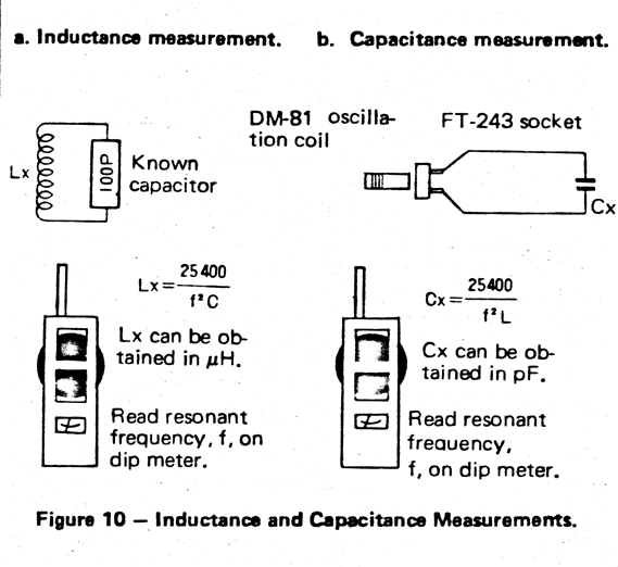
The value of an unknown inductor can be obtained in combination with a known capacitor by their resonant frequency, as illustrated in Figure 10. Likewise the value of an unknown capacitor can be calculated. The inductance (L), capacitance (C), and resonant frequency (f) are related as:
f = 1 / (2π √(LC))
This formula can be rewritten as
L = 25,400 / (f² C)
C = 25,400 / (f² L)
Where
L = inductance in µH
C = capacitance in pF
f = frequency in MHz
An inductance or capacitance can easily be calculated by substituting the known values into the above equations.
The oscillation coils supplied with your DM-81 are useful as the known inductor. Their inductances are
| BAND | INDUCTANCE |
| A | 1250 µH |
| B | 160 µH |
| C | 39 µH |
| D | 8.4 µH |
| E | 1.2 µH |
| F | 0.22 µH |
| G | 0.047µH |
In addition to all these applications, your DM-81 is usable in place of a receiver local oscillator in repairing or alignment, and is effective in other services as well. Also, your DM-81 can serve as a BFO for a receiver without one in receiving a CW or SSB signal. It is useful in a wide variety of situations. By fully understanding the principles of operation your DM-81's capabilities may be extended to other applications.
For an additional source of general information, the radio amateur's handbook is recommended.
VR1: 01 Bias adj.
By using G band, adjust VR1 so that the meter pointer deflection is maximum at 83MHz.
VR2: Meter zero adj.
Adjust VR2 so that the meter deflection is zero when the sensitivity control/power switch is set to just before the OFF position of the control.
VR3: Sensitivity adj.
Optimum position.
VR4: Battery voltage check adj.
Adjust VR4 so that the meter deflection comes to the left edge of the "B.C" zone at 7V when the FUNCTION switch is set to "B.C" position.
Ordering Spare Parts
When ordering replacement or spare parts for your equipment, be sure to specify the following:
Model and serial number.
Schematic number of the parts.
Printed circuit board number on which the part is located.
Part number and name, if known, and quantity desired.
Service
Should it ever become necessary to return this equipment for repair, pack in its original boxes and packing, and include a full description of the problems involved. Also include your telephone number. You need not return accessory items unless directly related to the service problem. Tag all returned items with your call for easy I.D.
Please mention the model and serial number of your unit in any correspondence, whether phone or written. For future reference, record this information in the space provided on the back cover of this manual.
NOTE:
When claiming warranty service, please include a photocopy of the bill of sale, or other proof of purchase showing the date of sale.
|
MAIN CHASSIS
|
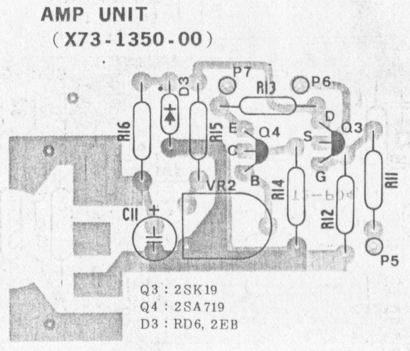
AMP UNIT (X73-1350-00)
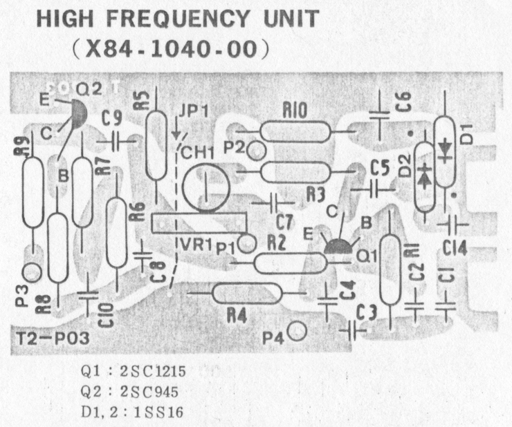
HIGH FREQUENCY UNIT (XB4-1040-00)
| |||||||||||||||||||||||||||||||||||||||||||||||||||||||||||||||||||||||||||||||||||||||||||||||||||||||||||||||||||||||||||||||||||||||||||||||||||||||||||||||||||||||||||||||||||||||||||||||||||||||||||||||||||||||||||||||||||||||||||||||||||||||||||||||||||||||||||||||||||||
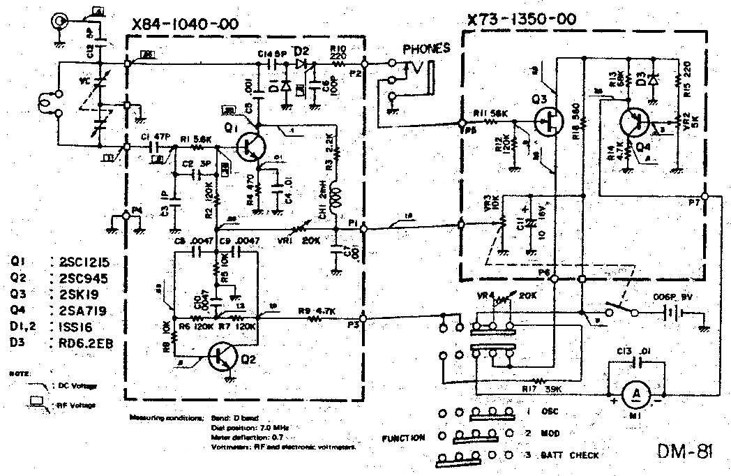
Unless otherwise specified, resistors are ¼W and ±5%. Also, the circuit elements may be changed without notice owing to a technical innovation.
Original manual copyright © 1980 by Kenwood Communications. Reproduced by explicit permission from Kenwood.
version copyright © 2003, 2009 by Dean K. Gibson. Reproduction for a charge is NOT authorized.